Chapter 5: Design of continuous RC beam
Get premium Best Assignment Writing Service Australia with expert-written, well-researched content aligned with Australian university standards. Review our free sample to assess our quality and academic excellence before ordering.
5.1 Introduction
The backbone of any structural system is reinforced concrete (RC) beams, and the so-called load is transferred to the vertical in the case of wall and column. Continuous beam in multi storey buildings is preferable in a building over simply supported beam, on the basis of providing increased structural efficiency, minimisation of deflections and expansion of the control of cracks. The current experiment is associated with the specific project of the design of a continuous T-beam on the 5 th floor in the zone, Zone 04 in particular with Axis 4 alignment and the length of 3.6 m without support. The beam is hyped based on the Australian Standard AS3600-2009, which includes normalisation of limit state principles in both strength and serviceability designs, together with the reinforcement detailing conditions.
The slab panel is loaded with dead loads, live loads and special water pressure loads due to the jacuzzi facility on the beam. The bending moment (M = 89.82 kNm) and shear force (V = 99.92 kN) have been obtained already with the help of the structural analysis. This chapter evolves these values into a step-by-step process of design to include geometry, load considerations, bending/shear design considerations to include serviceability cheques, and detail reinforcements to include detailing of the reinforcement.
5.2 Beam Geometry and Material Properties
5.2.1 Geometrical Parameters
Beam span (L): 3600 mm (centre-to-centre support).
Overall depth (h): 500 mm.
Web (stem) width (bw): 250 mm.
Effective depth (d):
d = h− cover− (bar diameter/2) =500−25−12=463 mm
Effective flange width (bf): Controlled by AS3600 provisions:
bw+2(6hf)=250+2(6×300)=3850 mm
bw+L/4=250+3600/4=1150 mm
Actual flange width = 3600 mm.
Governing limit: bf = 1150 mm.
5.2.2 Material Properties
Concrete grade: N32.
Characteristic compressive strength, f’c=32 MPa
Modulus of elasticity, Ec=30,100 MPa.
Unit weight = 24 kN/m³.
Reinforcement grade: D500N deformed bars.
Yield strength, fsy=500 MPa.
Modulus of elasticity, Es=200,000 MPa.
Concrete cover: 25 mm (Exposure class A2).
The beam geometry provides a 3.6 m span on a depth of 500 mm and a web of 250 mm that can provide a useful depth of 463 mm (Selvaraj & Chan, 2024). According to AS3600 the flange width is restricted to 1150 mm. Materials are N32 concrete, fc =32 Mpa and D500N steel reinforcement.
5.3 Load Assessment
5.3.1 Dead Loads (G)
Self-weight of slab (300 mm thick):
24×0.30=7.2 kN/m²
Finishes (ceramic tiles, gypsum ceilings, etc.): range 0.27 – 0.50 kN/m² depending on room type.
Average superimposed load considered = 0.33 kN/m².
5.3.2 Live Loads (Q)
Corridor: 4.0 kN/m² (AS1170.1).
Service room: 2.0 kN/m².
Kids’ room: 4.0 kN/m².
Jacuzzi: 2.0 kN/m² + 12.0 kN/m² water load.
5.3.3 Load Combinations (ULS)
Critical case:
Wu=1.2G+1.5Q
Using G = 7.53 kN/m², Q = 14 kN/m²:
Wu=1.2×7.53+1.5×14=30.04 kN/m²
5.3.4 Load Transfer to Beam
Tributary width = 1.8 m (half span of slab on each side).
Wu,beam=30.04×1.8=54.07 kN/m
Beam self-weight = 1.44 kN/m.
Wu=54.07+1.44=55.51 kN/m
That was calculated by structural analysis to show that the largest bending moment of 89.82 kNm occurs in the beam at ultimate loading. In this respect, the maximum shear force at the supports has the value of 99.92 kN (Hart, D’Amico & Pomponi, 2021). Such values underpins flexural and shear design, which need to fulfil the AS3600 strength and serviceability specifications.
5.4 Beam Design
Design Parameters
Length of beam = 3600 mm
Slab dimension = 3600 x 8000 mm
Concrete grade = N32 (fc = 32 MPa)
Steel grade = D500N (fsy = 500 MPa)
Exposure = A2 class
Concrete cover = 25 mm (AS 3600, table 4.10.3.2)
Laod calculation
Slab thickness = 300 mm
Concrete unit weight = 24 kN/m2
Gslab = 24 x 0.3 = 7.2 kN/m2
Long span = 8000 mm
L/d = 8000/300 = 26.67 ≤ 28 (pass)
Lx = 3600 mm
Ly = 8000 mm

Ly/ Lx = 8000/3600 = 2.22 > 2 (hence ok)
It can be called that spanning is one way (short direction).
Loads Analysis
Service room:
D.L-
Self weight = 7.2 kN/m2
Floor finish = 0.27 kN/m2 (due to ceramic tiles of 10 mm thickness)
Ceiling = 0.13 kN/m2 (gypsum, 13 mm)
Total D.L = 7.60 kN/m2
L.L-
Romm classificatio = A1
Live load (Q) = 2 kN/m2
Kids room:
D.L-
Self weight = 7.2 kN/m2
Floor finish = 0.3 kN/m2 (due to ceramic tiles)
Ceiling = 0.3 kN/m2 (gypsum)
Total D.L = 7.80 kN/m2
L.L-
Romm classificatio = A3
Live load (Q) = 4 kN/m2
Jacuzzi Area:
D.L-
Self weight = 7.2 kN/m2
Floor finish = 0.2 kN/m2 (due to ceramic tiles)
Ceiling = 0.13 kN/m2 (gypsum)
Total D.L (G) = 7.53 kN/m2
L.L-
Romm classification = A2 (toilet area)
Live load (Q) = 2 kN/m2
Water load (Qw) = 12 kN/m2
Total L.L = 14 kN/m2
Beam design parameter
Span = 3600 mm
As per AS3600,
Lh ≤ 10 in case of continuous beam
Hence, min depth, h = 3600/10 = 360 mm
Depth (h) = 500 mm
Width (bw) = 250 mm
Effective depth (d) = 500 – 25 – 12 = 463 mm
T-beam Parameters
Effective width of flange as per AS3600,
bef ≤ bw + 2×(6×hf)
bef ≤ 250 + 2 x (6 x 300)
bef ≤ 3850 mm
or
bef ≤ bw + L/4
bef ≤ 250 + 3600/4
bef ≤ 1150 mm
or
bef ≤ actual flange width
Hence, considering bef = 1150 mm
Load Combinations
G = 7.53 kN/m2
Q = 14 kN/m2
Load combination-
L.C1 = 1.2 G + 1.5 Q
L.C1 = 1.2 x 7.53 + 1.5 x 14
L.C1 = 30.04 kN/m2
L.C2 = 1.35 G
L.C2 = 1.35 x 7.53
L.C2 = 10.17 kN/m2
L.C3 = 0.9 G
L.C3 = 0.9 x 7.53
L.C3 = 6.78 kN/m2
Considering (wu) = L.C1 = 30.04 kN/m2
Beam Loading
Tributary area = 3.6/2 = 1.8 m
UDL on beam (wu,beam) = 30.04 x 1.8
wu,beam = 54.07 kN/m
Additional weight on the beam-
Beam below slab = (0.5 – 0.3) x 0.25 = 0.05 m2
Beam self-weight = 0.05 x 24 = 1.2 kN/m
Ultimate load = 1.2 x 1.2 = 1.44 kN/m
Total ultimate load (wu) = 54.07 + 1.44 = 55.51 kN/m
Structural Analysis
Maximum moment (M) = wu x L2/8
M = 55.51 x 3.62/8
M = 89.82 kNm
Maximum shear (V) = wu x L/2
V = 55.51 x 3.6/2
V = 99.92 kN
Slab ultimate load (wu) = 30.04 kN/m2
Effective span = 3.6 m
Load/width = 30.04 kN/m
Slab max moment (Mslab) = 30.04 x 3.62/8
Mslab = 48.67 kNm
Maximum shear (Vslab) = wu x L/2
V = 30.04 x 3.6/2
V = 54.07 kN
T-beam Section properties
Desihnm moment (M) = 89.82 kNm
Effective depth (d) = 463 mm
Web width (bw) = 250 mm
Effective flange width (bf) = 1150mm
Flange thickness (hf) = 300 mm
fc = 32 MPa
fsy = 500 MPa
Neutral axis check
Ac = bf x hf
Ac = 1150 x 300 = 345000 mm2
Max compressive force (Cc,max) = 0.85 x fc x Ac
Cc,max = 0.85 x 32 x 345000
Cc,max = 9384000 N
In equi;ibrium, T = C
As = M/(0.9 x fsy x d)
As = 89.82/(0.9 x 500 x 463)
As = 430 mm2
Tension force (T) = As × fsy
T = 430 x 500 = 215000 N
T < Cc,max (neutral axis in the flange)
Flexural Design
Neutral axis depth (ku) = √(2 Rn)
Rn = M/( φ × f'c × b × d²)
φ = 0.8
Rn = 89.82 × 10⁶/(0.8 × 32 × 1150 × 4632)
Rn = 0.0129
ku = 0.161
ku,max = 0.4 (AS3600) > ku (tensile failure that is acceptable)
As = (Rn x b x d)/(γ × fsy)
γ = ku(1 - ku/2)
γ = 0.161 (1 – 0.161/2) = 0.148
As = (.0129 x 1150 x 463)/(0.148 x 500)
As = 928 mm2
Steel Requirement
As,min = 0.25√f'c/fsy x b x d
As,min = 0.25√32/500 x 1150 x 463 = 691 mm2
As,max = 0.4 x f'c × b × d/(0.85 × fsy)
As,max = 0.4 x 32 x 1150 x 463/(0.85 x 500) = 40240 mm2
As,min < As < As,max
Providing 4N20 bars
As = 4 x 314 = 1256 mm2
Steel percentage (ρ) = (1256 x 100)/(1150 x 463) = 0.24%
Shear Design
Design shear (V) = 99.92 kN
As,provided = 1256 mm2
Shear capacity (Vuc) = β1 β2 β3 bv dv√f'c
β1 = 1.1 (1.6 - dv/1000)
β1 = 1.1 (1.6 – 463/1000) = 1.09, using 1.1
β2 = 1 (no axial force)
β3 = 1
bv = bw = 250 mm
dv = max of 0.72h or 0.9d
0.72h = 0.72 x 500 = 360
0.9d = 0.9 x 463 = 417
dv = 417 mm
Vuc = 1.1 x 1 x 1 x 250 x 417 x √32 = 637441 = 637.44 kN
Shear Reinforcement
Asv,min/sv ≥ 0.35 35bw/fsy = 0.35 x 250/500 = 0.175 mm2/mm
Providing N10, 2 leg stirrup, Asv = 2 x 78.5 = 157 mm2/mm
Max spacing = 0.5 dv = 0.5 x 417 = 208 mm
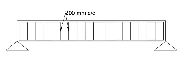
Providing N10 stirrup @ 200 mm c/c
5.5 Structural Analysis
5.5.1 Bending Moment
For a continuous beam approximated as fixed at supports:
M = (Wu L²)/8 = (55.51×3.6²)/ 8 =89.82 kNm
5.5.2 Shear Force
V= (WuL)/2 =55.51×3.62=99.92 kN
5.6 Flexural Design of Beam
5.6.1 Design Bending Strength
The flexural capacity is governed by:
Mu= ϕMn
Where:
ϕ=0.8 (strength reduction factor for flexure).
Mu =89.82 kNm
Therefore, required nominal moment capacity:
Mn=Mu/ϕ =89.82/0.8 =112.28 kNm
5.6.2 Steel Reinforcement Requirement
Lever arm approximation:
z ≈0.9d =0.9×463 =416.7 mm
Required steel area:
Ast =(Mn×106)/(fsy×z) = (112.28×10⁶)/ (500×416.7) ≈539 mm2
5.6.3 Selection of Bars
Provide 2 × N16 bars (area = 402 mm²).
Provide 1 × N12 bar (area = 113 mm²).
Total = 515 mm² (slightly less than 539 mm²).
Using 3 × N16 bars = 603 mm² (satisfies requirement with safety).
5.7 Shear Design
5.7.1 Nominal Shear Stress
τv=Vu/ (bwd) = (99.92×10³)/ (250×463) =0.86 MPa
5.7.2 Shear Capacity of Concrete
For N32 grade (AS3600):
Vuc=0.17√f’cbwd =0.17√32×250×463
Vuc=110.2kN
Since Vu=99.92 kN<Vuc, shear reinforcement is not strictly required, but minimum shear reinforcement (stirrups) must be provided as per code.
5.7.3 Shear Reinforcement Provision
Provide 2-legged N10 stirrups at 200 mm spacing across the span.
The flexural design permits the beam to hold safely, the ultimate moment of 89.82 kNm. The characterised strength reduction factor is 0.8; therefore, we need an 112.28 kNm nominal capacity. The area of steel needed is 539 mm2 and the lever arm used is that of 416.7 mm (Kazemi, Asgarkhani & Jankowski, 2023). At first, the demand was slightly higher than 515 mm2 that was given by two N16 bars and one N12 bar. Three N16 bars were taken to be safe as used and provided 603 mm2. Shear analysis indicated 99.92 kN which is less than 110.2 kN of concrete capacity. Nevertheless, according to AS3600, minimum shear reinforcement is obligatory and therefore 2-legged N10 stirrups at 200mm spacing were used (Aghasizadeh, Kari & Fayaz, 2022). This design attains flexural and shear strength requirement to ensure that the beam performs satisfactorily under ultimate loading and that it meets safety and the serviceability consideration.
5.8 Serviceability Checks
5.8.1 Deflection
Span-to-depth ratio check:
L/d=3600/463=7.8<10
Deflection control satisfied.
5.8.2 Crack Width
Beam adequacy under working conditions is checked with serviceability tests. The span/depth ratio is 7.8 which is significantly less than the AS3600 deflection control figure of 10. Adequate reinforcement and 25 mm cover also regulate the width of the crack to satisfy durability and exposure class A2 requirements to long-term performance and safety.
5.9 Reinforcement Detailing
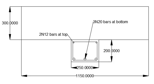
Bottom reinforcement (tension steel): 3 × N16 bars along the span.
Top reinforcement (support regions, negative moments): Provide 2 × N12 bars continuous.
Stirrups: 2-legged N10 @ 200 mm c/c.
Anchorage length: As per AS3600, development length for N16 bars = ~450 mm into supports.
Anchorage length: As per AS3600, development length for N16 bars = ~450 mm into supports.
Reinforcement detailing is one of the most important processes in beam design since calculation is converted into some constructible structures, that are safe and, at the same time, manageable. To take continuous RC T-beam, three N16 bars supply bottom tension precisely during the span so that they form against a positive bending moment. Two constant N12 bars, at the top position, will be used at the locations of support, which contain more negative moments. Shear resistance and ductility is improved by the provision of 2-legged N10 stirrups at the spacing of 200 mm along the beam (Gruyter, 2025). Anchorage is skewed based on AS3600, and an average length of development is about 450 mm on N16 bars that nip into supports. Adequate detailing should be provided in scaled drawings like; beam section, elevation, positioning of beams, and lap lengths to facilitate the right installation on construction.
5.10 Discussion
By the design it is shown that the slab and special hydrostatic applied loads can be safely supported by the continuous RC T-beam. The geometry (500 mm depth, 250 mm width, 1150 mm flange) is low enough in scope to provide sufficient stiffness. The flexural demand (89.82 kNm) corresponds to 3 x N16 bars, which is less than what is needed to provide lift-off shear, nonetheless shear is less than the concrete shear capacity and thus ductility and safety requirements are met through the use of stirrups. Serviceability cheques are used to ensure the deflections and width of the cracks is within reasonable limits.
5.11 Conclusion
The continuous RC beam along Axis 4 has been performed detailing in compliance with the AS3600-2009. Beam can sustain ultimate design loads including extra hydrostatic load of the jacuzzi and reserves safety and strength and serves. The reinforcement scheme that is adopted, 3 x N16 bottom bars, 2 x N12 top bars and N10 stirrups at 200 mm, gives sufficient resistance to flexure and shear and services.
This design excludes only the code but not a well-organised use of materials, which combines economy and safety. The continuous T-beam consequently assures sound workability in the structural system of Zone Z, where it favours the panel held by the slab and connotes sustainability.
Reference List
Journals
- Arya, C. (2022). Design of structural elements: concrete, steelwork, masonry and timber designs to eurocodes. CRC Press.[Retrieved from : https://www.taylorfrancis.com/books/mono/10.1201/9781003208037/design-structural-elements-chanakya-arya][Retrieved on : 5/9/25]
- Ellobody, E. (2023). Finite element analysis and design of steel and steel–concrete composite bridges. Elsevier.[Retrieved from : https://books.google.com/books?hl=en&lr=&id=6XqAEAAAQBAJ&oi=fnd&pg=PP1&dq=REINFORCED+CONCRETE+AND+STEEL+STRUCTURES+DESIGN&ots=1lynOhH02_&sig=ihkPq0TeMwqXYdpOb_U3jdtoaeE][Retrieved on : 5/9/25]
- El-Reedy, M. A. (2023). Steel-reinforced concrete structures: Assessment and repair of corrosion. CRC press. [Retrieved from :https://www.taylorfrancis.com/books/mono/10.1201/9781003407058/steel-reinforced-concrete-structures-mohamed-abdallah-el-reedy ][Retrieved on : 5/9/25]
- Gruyter, D. (2025). Structural steel design. Walter de Gruyter GmbH & Co KG.[Retrieved from : https://books.google.com/books?hl=en&lr=&id=rZxnEQAAQBAJ&oi=fnd&pg=PT16&dq=REINFORCED+CONCRETE+AND+STEEL+STRUCTURES+DESIGN&ots=jqCgtDj79B&sig=s7PpsCvDZvRMTuAjfxl5juaSOO8][Retrieved on : 5/9/25]
- Hart, J., D'Amico, B., & Pomponi, F. (2021). Whole‐life embodied carbon in multistory buildings: Steel, concrete and timber structures. Journal of Industrial Ecology, 25(2), 403-418.[Retrieved from : https://onlinelibrary.wiley.com/doi/abs/10.1111/jiec.13139][Retrieved on : 5/9/25]
- Huang, H., Yao, Y., Liang, C., & Ye, Y. (2022). Experimental study on cyclic performance of steel-hollow core partially encased composite spliced frame beam. Soil Dynamics and Earthquake Engineering, 163, 107499.[Retrieved from : https://www.sciencedirect.com/science/article/pii/S0267726122003475][Retrieved on : 5/9/25]
- Ivanov, M. L., & Chow, W. K. (2023, December). Structural damage observed in reinforced concrete buildings in Adiyaman during the 2023 Turkiye Kahramanmaras Earthquakes. In Structures (Vol. 58, p. 105578). Elsevier.[Retrieved from : https://www.sciencedirect.com/science/article/pii/S2352012423016661][Retrieved on : 5/9/25]
- Kazemi, F., Asgarkhani, N., & Jankowski, R. (2023). Machine learning-based seismic fragility and seismic vulnerability assessment of reinforced concrete structures. Soil Dynamics and Earthquake Engineering, 166, 107761.[Retrieved from :https://www.sciencedirect.com/science/article/pii/S0267726123000064 ][Retrieved on : 5/9/25]
- Pan, W., & Zhang, Z. (2023). Benchmarking the sustainability of concrete and steel modular construction for buildings in urban development. Sustainable cities and society, 90, 104400.[Retrieved from : https://www.sciencedirect.com/science/article/pii/S2210670723000112][Retrieved on : 5/9/25]
- Rabi, M., Shamass, R., & Cashell, K. A. (2022). Structural performance of stainless steel reinforced concrete members: A review. Construction and Building Materials, 325, 126673.[Retrieved from : https://www.sciencedirect.com/science/article/pii/S0950061822003646][Retrieved on : 5/9/25]
- Sadkovyi, V., Andronov, V., Semkiv, O., Kovalov, A., Rybka, E., Otrosh, Y., ... & Kovalov, P. (2021). Fire resistance of reinforced concrete and steel structures. Fire Resistance of Reinforced Concrete and Steel Structures, Kharkiv: РС ТЕСHNOLOGY СЕNTЕR, 180.[Retrieved from :https://papers.ssrn.com/sol3/papers.cfm?abstract_id=4008013 ][Retrieved on : 5/9/25]
- Selvaraj, S., & Chan, T. M. (2024). Recommendations for implementing circular economy in construction: direct reuse of steel structures. Journal of constructional steel research, 214, 108439.[Retrieved from : https://www.sciencedirect.com/science/article/pii/S0143974X23006661][Retrieved on : 5/9/25]