Construction Measurement of Architectural and M&E Works
Question 1a
In-situ Finishes
SMM Clause 8.01 - In-situ Finishes
General Ceiling Areas: This refers to the total square m of the area in contact with base not including the opening(s) = 0.5m2
Beam Sides and Soffits: The measurements have different values in equals squares metres (m2), and specifies the values of the width.
Students looking for Best Assignment Help Australia can refer to this construction assignment sample to understand construction measurement principles, SMM standards, quantity take-off calculations and architectural work specifications
SMM Clause 8.02 - Width Classifications for Beams
Designation (Width) Beam sides and soffits:
- Not exceeding 150mm wide
- 150-300mm wide
- 300-600mm wide
- Exceeding 600mm wide
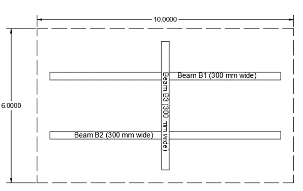
Measurement Example - In-situ Finishes
General Ceiling Area: Total area = 10.0m x 6.0m = 60.0m2
Suspend beam area (beam suspended, beam is not an opening) no deduction beam areas.
Beam sides, soffits (must be broader than 300 mm)
- Beam B1 soffit: 10.0 m × 0.3 m = 3.0 m²
- Beam B1 sides: (10.0 m × 0.25 m) × 2 = 5.0 m²
- Beam B2 soffit: 10.0 m × 0.3 m = 3.0m²
- Beam B2 sides: (10.0 m × 0.25 m) × 2 = 5.0 m²
- Beam B3 soffit: 5.0 m × 0.3 m = 1.5 m²
- Beam B3 sides: (5.0 m × 0.25 m) × 2 = 2.5 m²
Total beam area = 20.0m²
(ii) Preformed Tile Finishes
SMM Clause 9.01 - Preformed Tile Finishes
General Ceiling Areas: in square metres (m2) to the covered area, including the tile cutting and fitting allowance.
Beam Sides and Soffits: One at a time (linear metres (m) or square metres (m2) of narrow sections, or of wider sections).
SMM Clause 9.02 - Tile Finish Classifications
Different measurements on the basis of application:
- Linear measurement - For widths ≤ 300mm
- Area measurement - For widths > 300mm
- Additional items - Cutting, fitting, and waste allowances
Measurement Example - Preformed Tile Finishes
General Ceiling Area:
Total area = 10.0m × 6.0m = 60.0m² (including 5% cutting allowance = 63.0m²)
General Ceiling Area:
Completely cut area = 10.0 m x 6.0 m = 60.0m2 (5% cut off allowance = 63.0m2)
Beam Sides and Soffits:
- Beam B1 soffit (300mm) - 10.0 m (linear metres)
- Beam B1 sides (250mm) - 10.0m × 2 = 20.0 m (linear metres)
- Similar for other beams
Linear measurement of beam = 70.0 m
Reasons for Different Measurement Approaches
| Aspect | In-situ Finishes | Preformed Tile Finishes |
|---|---|---|
| General Ceiling | Area (m²) - no deductions for beams | Area (m²) + cutting allowance |
| Beam Soffits | Area (m²) by width categories | Linear (m) if ≤300mm, Area (m²) if >300mm |
| Beam Sides | Area (m²) by width categories | Linear (m) if ≤300mm, Area (m²) if >300mm |
| Waste Allowance | Minimal - included in rate | Explicit cutting and fitting allowance |
| SMM Clauses | 8.01, 8.02 | 9.01, 9.02 |
Question 1b
SMM Clause 11.02f - Timber Plates
Timber plates (wall plates, sole plates, head plates) measured in linear metres (m) with joint allowances for:
- Lap joints: 10% allowance for overlaps
- Scarf joints: 5% allowance for end connections
- Corner connections: Additional length for corner laps
SMM Clause 11.02g - Bearing Timber
Bearing timber (joists, rafters, beams) measured in linear metres (m) with joint allowances for:
- Scarfed joints: 5% allowance for lengthening joints
- Housing joints: No additional allowance (included in bearing length)
- Notching and cutting: Measured separately
Joint Types & Applications
Lap Joint (Timber Plates)
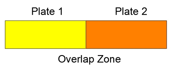
Usage: Wall plates, sole plates at corners and extensions
Reason for 10%: Requires significant overlap (typically 600-1000mm) for structural integrity
Scarf Joint (Timber Plates)
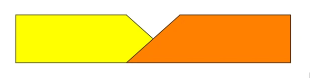
Usage: End-to-end joining of plates in straight runs
Reason for 5%: Minimal waste in cutting and fitting scarf angles
Scarfed Joint (Bearing Timber)
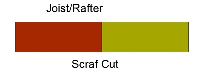
Usage: Extending the length of joists, rafters, and beams
Reason for 5%: Standard cutting allowance for end preparation
Practical Examples
Example 1: Wall Plate System
Building perimeter: 20m × 12m rectangular building
Available timber lengths: 6m standard lengths
Calculation:
- Total perimeter = (20 + 12) × 2 = 64m
- Lap joints at 4 corners = 10% allowance required
- Scarf joints in long runs = 5% allowance required
- Wall plate quantity = 64 x 1.10 = 70.4 m
Joint Analysis:
- 20m sides: 4 pieces of 6m = 24m (need 2 scarf joints)
- 12m sides: 2 pieces of 6m = 12m (need 1 scarf joint)
- 4 corner lap joints require additional material
Example 2: Floor Joists (Bearing Timber)
Joist span: 8m clear span
Length of timber available: 6m standard length.
Joist spacing: 25 joists with a centre spacing of 400mm.
Calculation:
- Length required per joist = 8.2m (including bearing).
- Required scarfed extension 6m + 2.5m pieces.
- Scarf joint allowance = 5%
- Joint Quantity = 25 x 8.2 x 1.05 = 214.7 m
Example 3: Mixed Joint System
Roof Structure: plate and rafters hip roof
All Plates (SMM 11.02f):
- Perimeter plates: 60m X 1.10 = 66m (lap joints on corners)
- Internal plates: 20m x 1.05 = 21m (scarf joints only)
- Total plates: 87m
Rafters (SMM 11.02g):
- Common rafters: 45 x 4.5m = 202.5m
- Hip rafters: 26m (scarf to be scarfed): 4 x 6.5m.
- Scarf allowance: (202.5 + 26) x 1.05 = 239.9m
- Total rafters: 240m
Summary of Joint Allowances
| Joint Type | Timber Type | SMM Clause | Allowance | Reason |
|---|---|---|---|---|
| Lap Joint | Plates | 11.02f | 10% | Substantial overlap required |
| Scarf Joint | Plates | 11.02f | 5% | End cutting and fitting |
| Scarfed Joint | Bearing Timber | 11.02g | 5% | Length extension cutting |
| Housing Joint | Bearing Timber | 11.02g | 0% | Included in bearing length |
Question 2
Project Specifications
| Roof Dimensions | 15,000mm × 6,500mm (Plan) |
| Roof Pitch | 45 degrees |
| Tiles | Hugenot HP 10 clay interlocking tiles |
| Timber | All structural timber shall be keruing preserved |
| Rafter Spacing | 600mm c/c |
| Batten Spacing | 300mm c/c |
| Underlay | Two layers bitumen felt, 12mm thick overall |
Key Calculations
- Length of rafter = 3250 / cos45° = 4599 mm ≈ 4.6 m
- Rafter number = (15000 – 200)/600 + 1 = 26 rafters
- Area of roof = 15 x 4.6 x 2 = 138 m2
- Batten per slope = 4600/300 = 16
Part (a): Roof Coverings Including Associate Underlays
| Length | Width | Height / Thickness | Description |
|---|---|---|---|
| 15.0m | 4.6m | - | Hugenot HP 10 clay interlocking roof tiles, fixed to timber battens with galvanized nails, tiles to protrude 75mm from fascia board over gutter, including 5% waste allowance (2 slopes × 69m² × 1.05) |
| 15.0m | - | 275mm dia | Ridge tiles, 275mm diameter half round, matching Hugenot HP 10 tiles, bedded in cement sand mortar (15,000mm ÷ 300mm spacing) |
| 30.0m | - | - | Special eave tiles, matching Hugenot HP 10, at eaves of roof (15m × 2 eaves) |
| 18.4m | - | - | Special verge tiles, matching Hugenot HP 10, at gable ends (4.6m × 2 slopes × 2 gables) |
| 15.0m | 50mm | 30mm | Timber battens, 50 × 30mm, keruing preserved, fixed @ 300mm c/c to rafters with galvanized nails (32 battens × 15m each) |
| 15.0m | 4.6m | 12mm | Underlay comprising two layers of bitumen felt, 12mm thick overall, including 10% lap allowance (138m² × 2 layers × 1.10) |
| 15.0m | 4.6m | 50mm | Roof insulation, 50mm thick fiberglass with double sided sisalation foil 450, including 5% waste (138m² × 1.05) |
| 15.0m | 4.6m | - | Fabric mesh 3325 laid on underside of roof covering to support insulation |
Part (b): Structural Timber Members Including Wall Plates
| Length | Width | Height / Thickness | Description |
|---|---|---|---|
| 4.6m | 75mm | 200mm | Common rafters, 75 × 200mm, keruing preserved timber, spaced @ 600mm c/c, including 5% joint allowance for scarfed joints (26 rafters × 4.6m × 1.05) |
| 3.25m | 75mm | 175mm | Ceiling joists, 75 × 175mm, keruing preserved timber, spaced to match rafters @ 600mm c/c, including 5% joint allowance for scarfed joints (26 joists × 3.25m × 1.05) |
| 15.0m | 75mm | 300mm | Ridge board, 75 × 300mm thick, keruing preserved timber, including 5% joint allowance for scarfed joints (15m × 1.05) |
| 15.0m | 75mm | 150mm | Wall plates, 75 × 150mm, keruing preserved timber, placed on eaves brick walls between gable walls, including 10% joint allowance for lap joints (2 plates × 15m × 1.10) |
Part (c): Fascia, Barge, Soffit Boards and Timber Bearers
| Length | Width | Height / Thickness | Description |
|---|---|---|---|
| 15.0m | 275mm | 30mm | Fascia board, 275 × 30mm thick hardboard, at eaves including 2% joint allowance for butt joints (2 eaves × 15m × 1.02) |
| 4.6m | 275mm | 30mm | Barge board, 275 × 30mm thick hardboard, at gable ends including 2% joint allowance for butt joints (2 gables × 4.6m × 1.02) |
| 15.0m | 300mm | 20mm | Eaves soffit boards, installed at eaves, including 5% waste allowance (15m × 0.3m × 2 eaves × 1.05) |
| 4.6m | 300mm | 20mm | Verge soffit boards, installed at gable verges, including 5% waste allowance (4.6m × 0.3m × 2 gables × 1.05) |
| 300mm | 50mm | 50mm | Vertical timber bearers, 50 × 50mm × 300mm long, keruing preserved, to support soffit boards at eaves @ 600mm c/c (15m × 2 eaves ÷ 0.6m spacing) |
| 300mm | 50mm | 50mm | Horizontal timber bearers, 50 × 50mm × 300mm long, keruing preserved, to support soffit boards at verges @ 600mm c/c (4.6m × 2 gables ÷ 0.6m spacing) |
| - | - | - | Three coats of enamel paint to soffit boards, primer, undercoat and finishing coat (12.4m² total soffit area × 3 coats) |
| - | - | - | Galvanized nails, screws, and fixings for fascia, barge and soffit board installation, complete with all necessary brackets and fixings |
| 100mm | - | - | 100mm half round gutter, complete with brackets, joints, and end caps (15m × 2 eaves) |
Accurate measurement and quantity take-off are essential skills in construction projects. Students can also explore Quantity Surveying Assignment Help to understand measurement standards, material calculations and construction cost estimation
Question 3a
Differences
| Metal Doors & Frames | Timber Doors & Frames |
|---|---|
SMM Clause 12.01 - Metal Doors
|
SMM Clause 11.01 - Timber Doors
|
SMM Clause 12.02 - Metal Door Frames
|
SMM Clause 11.02 - Timber Door Frames
|
SMM Clause 12.03 - Metal Door Hardware
|
SMM Clause 11.03 - Timber Door Hardware
|
Question 3b
Project Specifications
| Door Type | 45mm thick single leaf Hercules Tacam blast resistant steel door |
| Fire Rating | 4H fire rated complying with SS 332:2007 |
| Door Dimensions | 900mm (W) × 2100mm (H) × 45mm (thick) |
| Frame Dimensions | 1013mm (W) × 2196mm (H) × 150mm (deep) |
| Frame Material | Galvanized steel jamb with integral fixing lugs |
| Hardware | Proprietary Tacam multi-point lockset, heavy duty hinges, flush bolt, door handle |
SMM Reference
- SMM Clause 12.01: Metal doors measured as complete items (nr) with dimensions and specifications stated
- SMM Clause 12.02: Metal door frames measured as complete frame sets (nr)
- SMM Clause 12.03: Hardware measured as complete sets or individual items (nr)
Quantity Take-Off Table
| Particulars | Length | Width | Height / Thickness | Description |
|---|---|---|---|---|
| METAL DOOR LEAF | ||||
| Metal door leaf | 900 mm | 2100 mm | 45 mm | 45mm thick single leaf blast resistant steel door, Hercules Tacam or approved equivalent, 4H fire rated complying with SS 332:2007, complete with factory applied primer finish, size 900mm × 2100mm × 45mm thick |
| METAL DOOR FRAME | ||||
| Metal door frame | 1013 mm | 2196 mm | 150 mm | Galvanized steel door frame complete set, hollow core construction as per specifications, size 1013mm × 2196mm × 150mm deep, including integral fixing lugs for precast concrete wall, weather seal rebates (45mm and 50mm depths), and factory galvanized finish |
| Threshold and sill | 1 set | 1 set | 1 set | Door frame threshold and sill assembly, galvanized steel construction, complete with drainage channels and weather sealing, sized to suit frame opening |
| DOOR HARDWARE | ||||
| Lockset | 1 set | 1 set | 1 set | Proprietary Tacam multi-point lockset complete with cylinder, keeps, striking plates, and all necessary components for blast resistant door system, factory tested and certified |
| Hinges | 3 sets | 3 sets | 3 sets | Heavy duty steel hinges, Tacam approved, minimum 100mm × 75mm × 3mm thick, complete with stainless steel pins and bushes, suitable for blast resistant door application |
| Flush bolt | 1 set | 1 set | 1 set | Flush bolt system, heavy duty construction, complete with top and bottom shoot bolts, operating mechanism, and all fixing accessories |
| Door handle | 1 set | 1 set | 1 set | Door handle set, Tacam approved, heavy duty lever handle with back plate, complete with cylinder escutcheon, emergency release mechanism, and all fixing screws |
| SEALING AND WEATHERPROOFING | ||||
| Weather sealing | 1 set | 1 set | 1 set | Weather sealing system complete, including perimeter seals for 45mm and 50mm rebates, threshold seal, and all necessary gaskets for blast resistant performance |
| Fire sealing | 1 set | 1 set | 1 set | Fire sealing system, intumescent strips and seals as required for 4H fire rating compliance, complete with smoke seals and all fixing accessories |
| INSTALLATION AND FIXING | ||||
| Concrete wall fixing | 1 set | 1 set | 1 set | Concrete wall fixing system, including anchor bolts, chemical anchors, and all necessary fixings for securing frame to precast concrete wall structure, complete with load distribution plates |
| Installation and commissioning | 1 set | 1 set | 1 set | Installation, adjustment, and commissioning of complete door system, including testing of all functions, verification of blast resistance and fire rating compliance, and provision of test certificates |
| FINISHING AND PROTECTION | ||||
| Final finishing | 1 set | 1 set | 1 set | Final finishing and protection of door system, including touch-up of any installation damage, application of final protective coatings, and cleaning of all surfaces |
Reference List
- Fatai, O.B., Ohis, A.C., Liphadzi, M., Stephen, R.M. and Bola, O.S., 2023. Assessment of lean guided construction project monitoring and evaluation practices: issues and challenges. In Proceedings of the 31st Annual Conference of the International Group for Lean Construction (IGLC31) (pp. 1127-1137).
- Hariyanto, V.L., Daryono, R.W., Hidayat, N., Prayitno, S.H. and Nurtanto, M., 2022. A Framework for Measuring the Level of Achievement of Vocational Students Competency of Architectural Education. Journal of Technology and Science Education, 12(1), pp.157-171.
- Jalil, A.B.A., Md Fazil, F.B., Hashim, M.A.S.B. and Nawi, N.B., 2023, August. Mechanical and Electrical Issues in Prefabricated Housing; Their Real Causes and Corrective Steps. In International Conference on Electrical, Control & Computer Engineering (pp. 247-261). Singapore: Springer Nature Singapore.
- Sazali, M.S., Ariffin, H.L.T., Mohd, N.I., Bahrodin, M.B. and Yusoff, N.N.S.M., 2025, June. Occupational Safety and Health in Construction Industry (Management) 2017: Awareness among Construction Stakeholders. In IOP Conference Series: Earth and Environmental Science (Vol. 1509, No. 1, p. 012009). IOP Publishing.
- Tengan, C. and Aigbavboa, C., 2021. Validating factors influencing monitoring and evaluation in the Ghanaian construction industry: a Delphi study approach. International Journal of Construction Management, 21(3), pp.223-234.
- Tengan, C., Aigbavboa, C. and Thwala, W.D., 2021. Construction project monitoring and evaluation: An integrated approach. Routledge.